

Boom Cylinder Holding Valve Test: Why Test at Mid-Stroke
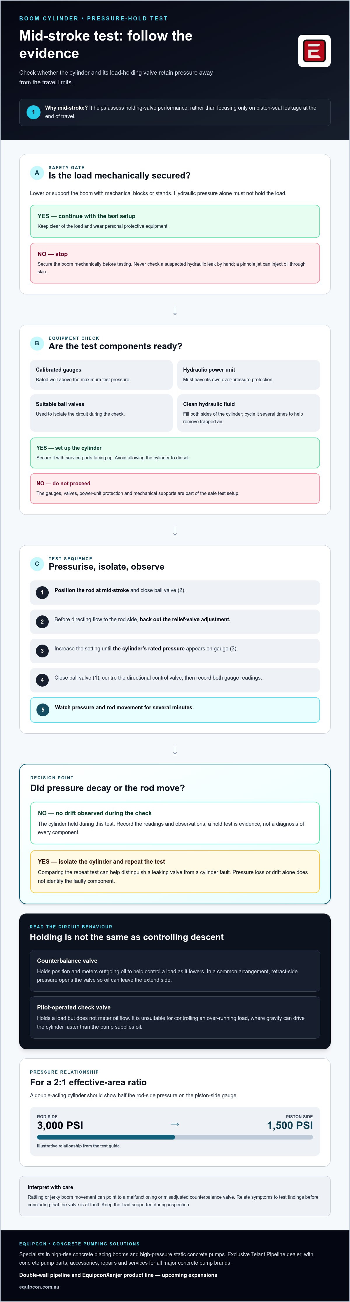
A mid-stroke test can reveal more about a boom’s ability to hold position than an end-of-stroke check alone. To understand how to perform a boom cylinder holding valve test, position the piston rod at mid-stroke, pressurise the cylinder to its rated pressure, then isolate the circuit and monitor pressure and rod movement for several minutes. This helps distinguish holding-valve performance from piston-seal leakage.
A boom that drifts or moves unexpectedly can disrupt work and indicate a problem in the load-holding system. The test shows whether the cylinder holds under pressure and helps explain how a counterbalance valve controls a load as it lowers.
This guide explains why mid-stroke matters, how load-holding and counterbalance valves work, and what pressure loss or rod movement may indicate. It also covers why safe isolation and careful interpretation are essential when assessing a boom cylinder.
Preventing cylinder drift and uncontrolled movement
A mid-stroke pressure-hold test checks whether the boom cylinder and its holding valve retain pressure away from the travel limits. You’ll need calibrated hydraulic pressure gauges rated well above the maximum test pressure, suitable ball valves, a hydraulic power unit with over-pressure protection, and mechanical blocks or stands. Wear personal protective equipment, and never check a suspected hydraulic leak by hand: a pinhole jet can inject oil through skin.
Secure or lower the boom with mechanical supports before testing; hydraulic pressure alone must not hold the load. Secure the cylinder with its service ports facing up, fill both sides with clean hydraulic fluid, then cycle it several times to help remove trapped air. Take care not to diesel the cylinder. Position the rod at mid-stroke and close ball valve (2).
Before directing flow to the rod side, back out the relief-valve adjustment. Increase the setting until the cylinder’s rated pressure appears on gauge (3). Then close ball valve (1) and centre the directional control valve. This sequence assumes the power unit has its own over-pressure protection. Record both gauge readings and watch for pressure decay and rod movement over several minutes.
Pressure-hold and rod-drift observations help identify a holding problem, but don’t diagnose the faulty component alone. If drift appears, isolate the cylinder and repeat the test to distinguish a leaking valve from a cylinder fault. A double-acting cylinder with a 2:1 effective-area ratio should show half the rod-side pressure on the piston-side gauge. For example, 3,000 PSI on the rod side corresponds to 1,500 PSI on the piston side.
Counterbalance valve operation
Hydraulic crane load-holding systems typically use either a pilot-operated check valve or a counterbalance valve. A counterbalance valve does more than hold position: it meters outgoing oil to help control the load as it lowers. This distinction matters when assessing boom movement, because the valve must both hold the load and regulate descent smoothly.
In a common arrangement, pressure on the cylinder’s retract side opens the counterbalance valve, allowing oil to leave the extend side. The valve controls the load as the boom lowers, rather than letting gravity pull it down freely. If the extend line or hose fails, pressure on the retract line is still needed to open the valve, so descent remains controlled in this arrangement.
Counterbalance valves can also provide pressure relief, unlike pilot-operated check valves. Where counterbalance valves are fitted on both cylinder sides, pressure can relieve through the control valve once it reaches a valve setting. Set points may need adjustment after installation on an individual crane so the valve suits the hydraulic system and load.
One reported application used a 3-to-1 pilot ratio: the valve was described as opening at 3000 psi without pilot assist and 1000 psi with pilot assist. Those figures illustrate how pilot pressure changes the opening threshold, not a universal boom specification. Rattling or jerky boom movement can point to a malfunctioning or misadjusted counterbalance valve; relate those symptoms to the test findings before concluding the valve is at fault.
Load holding valve safety and performance
A load-holding valve is a safety component, not a substitute for sound testing practice. Pilot-operated check valves can limit drift and help restrain movement after a hose failure, but they don’t meter oil flow. They’re therefore unsuitable for controlling an over-running load, where gravity can drive the cylinder faster than the pump supplies oil. A counterbalance valve performs that metering role.
Clean fluid matters. Load-holding valves have tight internal clearances, so contamination can interfere with the components that control flow and retain pressure. Treat a pressure drop or unexpected boom movement as a reason to investigate the entire circuit, not as proof that the valve alone has failed. Wear can affect a valve’s internal components, which require periodic replacement to maintain proper function.
A separate boom-cylinder check can help distinguish piston-seal leakage from a leaking load valve. With the boom raised and the piston side pressurised, observe the open rod-side hose. If the boom drops and oil exits that hose, the piston seals may be leaking. If the boom drops without oil coming from the hose, a leaking load valve is indicated. Keep clear of the load and use suitable mechanical support during inspection.
Valve location also affects protection and serviceability. An external manifold is easier to replace if it fails, but it can be exposed to impacts and the elements. Check for damage and consider the valve’s position when assessing a recurring fault. If pressure loss or drift persists, discuss your equipment test findings before returning the boom to work.
Equipcon: Mobile Concrete Pumps
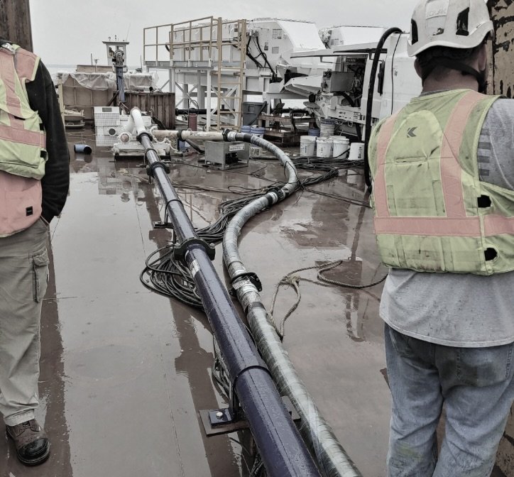
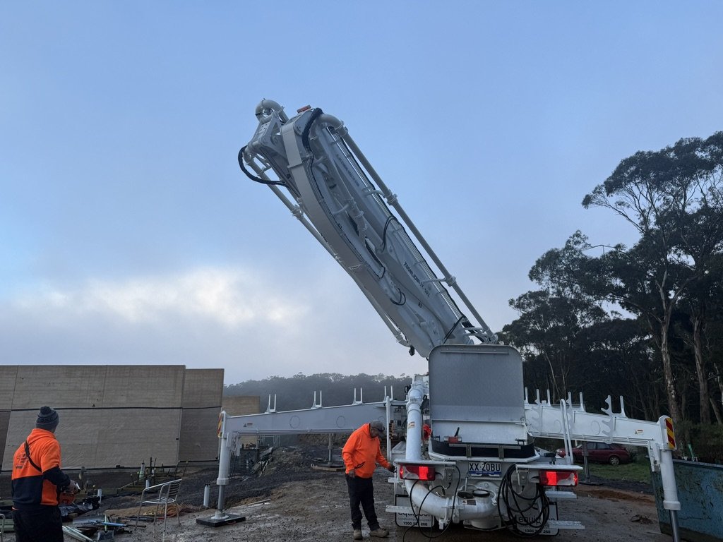
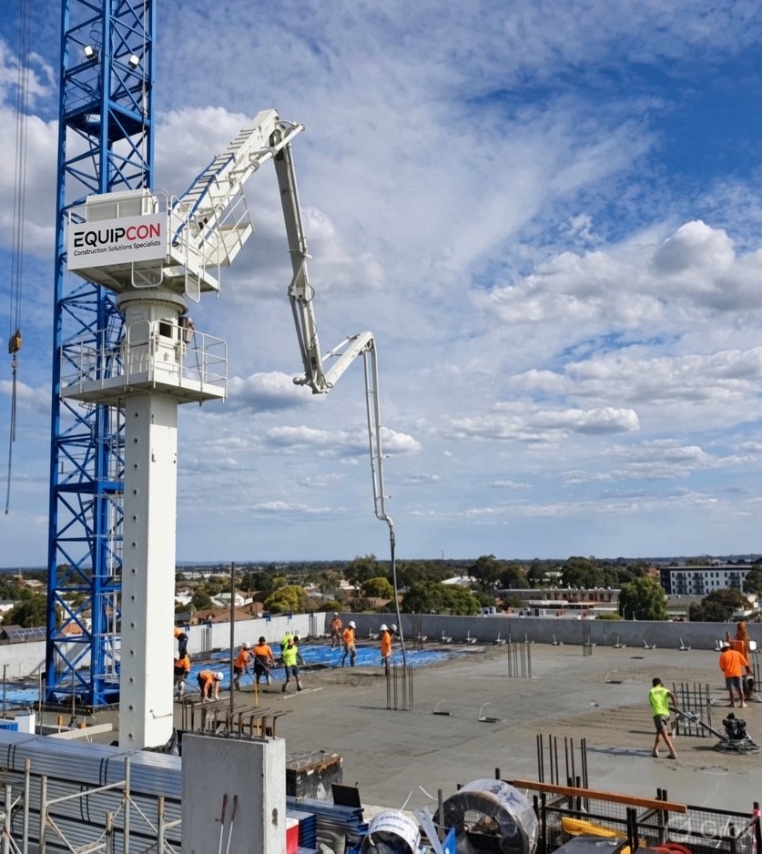
Equipcon specialises in high-rise concrete placing booms and high-pressure static concrete pumps, alongside mobile and stationary concrete pumps. As an authorised equipment reseller and exclusive Telant Pipeline dealer, Equipcon supports concrete placement needs with equipment, pump spare parts, pipeline and accessories.
Equipcon also provides concrete pump repairs and services for all major concrete pump brands. Its upcoming expansions include a double-wall pipeline and the EquipconXanjer product line, extending its focus on concrete pumping equipment and related solutions.
If your test has highlighted a concern or you’re planning equipment needs, contact Equipcon to discuss concrete pumps, placing booms, parts or repairs.
Use test findings to plan the next step
Understanding how to perform a boom cylinder holding valve test is only part of the assessment. Treat readings and observed movement as diagnostic evidence to guide further inspection and equipment planning. A drift result can help focus attention on the cylinder and its holding circuit instead of prompting unnecessary equipment replacement.
Equipcon supplies mobile and stationary concrete pumps and concrete placing booms for construction operations. If your assessment raises broader questions about concrete pumping equipment, consider how the machine and its components fit your site requirements.
Contact Equipcon about valve testing to discuss your equipment needs. A measured, evidence-led next step helps keep your decisions practical and focused.
Frequently Asked Questions
Why test at mid-stroke?
Testing at mid-stroke assesses pressure retention while the piston sits between its travel limits. An end-of-stroke bypass test instead focuses on leakage past the piston seal at the cylinder’s travel limit. These tests answer different diagnostic questions, so a mid-stroke result helps assess holding performance without treating an end-position seal check as a substitute.
What is a boom cylinder holding valve test and what does it diagnose?
A pressure-hold assessment checks whether a boom cylinder circuit retains pressure and whether the rod moves while isolated. A pressure change or drift signals a holding issue, but doesn’t identify the failed part on its own. Isolating the cylinder and repeating the test can help distinguish a leaking valve from a cylinder fault, such as a piston-seal problem.
What safety precautions are required before testing a boom cylinder holding valve?
Lower or mechanically support the boom before testing; never rely on hydraulic pressure alone to hold the load. Wear personal protective equipment and use calibrated gauges rated well above the maximum test pressure. Keep hands clear of suspected leaks, since a pinhole jet can inject hydraulic oil through skin. Make sure the power unit’s over-pressure protection is in place.
What are the step-by-step procedures for testing a boom cylinder holding valve?
To perform a boom cylinder holding valve test, follow the specified circuit arrangement and the cylinder’s rated pressure. A typical sequence is:
Secure the load mechanically and prepare the cylinder with clean fluid.
Cycle the cylinder to help remove trapped air, then position the rod at mid-stroke.
Pressurise to the cylinder’s rated pressure, isolate the circuit and centre the directional valve.
Record both gauge readings and observe pressure and rod movement over time.
Use the power unit’s over-pressure protection throughout.
How do you test a boom cylinder holding valve for internal leakage or drift?
To test for leakage, isolate the cylinder and monitor gauge pressure alongside rod position. Record any movement and pressure change under the same test conditions, then repeat the test to help distinguish a leaking valve from a cylinder fault. In a separate check, boom drop accompanied by oil exiting the open rod-side hose points to possible piston-seal leakage.
Comments